Blogs

What is the difference between Allen Bradely and Siemens PLCs?

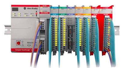
What is the difference between Allen Bradely and Siemens PLCs? General Overview: Allen-Bradley: Market Focus: Predominantly used in the U.S. PLC Families: ControlLogix, CompactLogix, MicroLogix. Programming: Known for user-friendly programming environments, making it easier to learn and implement. Installation: Requires dedicated Allen-Bradley racks and power supplies. Communication: Primarily supports North American protocols (Device Net, ControlNet, Ethernet/IP). Siemens: Market Focus: Predominantly used in Europe. PLC Families: SIMATIC S7-200, S7-300, S7-400. Programming: More complex, requiring a higher level of expertise. Installation: Can be powered by any 24V DC power supply and does not require a rack. Communication: Primarily supports European protocols (PROFIBUS, MODBUS). Specific Product Comparisons: Allen-Bradley ControlLogix vs. Siemens S7-400: Memory: ControlLogix: Ranges from 2MB to 20MB depending on the model (5570 or 5580 series). S7-400: Memory ranges significantly with models offering from 96KB to 4MB, with additional memory dedicated to instructions. I/O: ControlLogix: Modular, chassis-based system supporting distributed I/O with high scalability. S7-400: Modular but not chassis-based, with a limit of 21 expansions, supporting up to 16,384 digital I/O and 4,000 analog I/O. Communication: ControlLogix: Offers extensive communication flexibility, including EtherNet/IP, ControlNet, DeviceNet, and more. S7-400: Connects to Industrial Ethernet and PROFIBUS, with limited support for other protocols. Safety: ControlLogix: Offers embedded safety features with GuardLogix controllers. S7-400: Has integrated safety features but was initially reliant on add-on modules. Allen-Bradley CompactLogix vs. Siemens S7-300: Memory: CompactLogix: Ranges from 0.6MB to 10MB depending on the model. S7-300: Memory ranges from 32KB to 2560KB, with the use of a Micro Tested Memory Card for backup. I/O: CompactLogix: Designed to support distributed I/O with local and node expansions. S7-300: Modular system with a total digital I/O of 1024 and analog I/O of 256. Communication: CompactLogix: Supports protocols like EtherNet/IP, DeviceNet, and USB client. S7-300: Offers a wide range of communication protocols including PROFIBUS and Industrial Ethernet. Allen-Bradley MicroLogix vs. Siemens S7-200: Memory: MicroLogix: Memory ranges from 1KB to 10KB for user programs, with additional data logging capabilities. S7-200: Memory ranges from 4KB to 16KB, with consistent battery backup across all models.   I/O: MicroLogix: Offers more digital I/O and greater flexibility for analog I/O expansion. S7-200: Limited analog I/O through expansion modules, with I/O ranging from 6 In/4 Out to 24 In/16 Out. Communication: MicroLogix: Offers RS232, DeviceNet, Ethernet/IP, and more, with superior communication flexibility. S7-200: Limited to RS-485, with additional support for MODBUS TCP/IP on certain models. Key Takeaways: User-Friendliness: Allen-Bradley is generally easier to program and debug, making it a better choice for environments where ease of use is paramount. Flexibility in Communication: Allen-Bradley offers more flexibility in communication methods, especially in North America. Siemens, while supporting a wide range of protocols, is more focused on European standards. Hardware Requirements: Allen-Bradley requires dedicated hardware components, whereas Siemens offers more flexibility in power supply and installation. Market Preference: Choose Allen-Bradley for North American projects and Siemens for European projects, or when working with systems already based on Siemens technology.  
PLC Communication Protocols

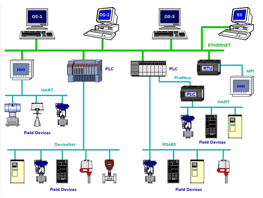
PLC Communication Protocols Profibus What is Profibus? Profibus (Process Field Bus) is a standard for fieldbus communication in automation technology. It is used to connect various devices and systems in industrial automation environments. Profibus allows for real-time communication between devices like sensors, actuators, and controllers. Devices Connected: Maximum Devices: Up to 126 devices can be connected on a single Profibus network. Range: Distance: Up to 1,200 meters (1.2 km) for Profibus DP (Decentralized Peripherals), depending on the baud rate. Voltages: Minimum Voltage: 9 V DC. Maximum Voltage: 32 V DC. Profinet What is Profinet? Profinet is an Ethernet-based protocol for industrial automation. It integrates field-level communication with the higher-level enterprise systems and provides real-time data transfer. Profinet supports a wide range of devices and applications, including both real-time and non-real-time communication. Devices Connected: Maximum Devices: The number of devices is theoretically unlimited but practically limited by network design and performance. Range: Distance: Limited by Ethernet standards, typically up to 100 meters for standard Ethernet cables, but can be extended using network switches and fiber optics. Voltages: Minimum Voltage: 9 V DC (depends on the specific Profinet device). Maximum Voltage: 32 V DC (typical for industrial Ethernet devices). RS-232 What is RS-232? RS-232 (Recommended Standard 232) is a serial communication protocol used for point-to-point communication between devices. It is commonly used for connecting computers to peripheral devices such as modems and serial ports. Devices Connected: Maximum Devices: Typically connects two devices (point-to-point communication). Range: Distance: Up to 15 meters (50 feet) at a maximum baud rate of 115200 bps. Distance can be extended with lower baud rates. Voltages: Minimum Voltage: -15 V DC. Maximum Voltage: +15 V DC. RS-485 What is RS-485? RS-485 is a standard for serial communication that supports multi-point systems. It is used in industrial environments for long-distance and high-speed communication between multiple devices. Devices Connected: Maximum Devices: Up to 32 devices per network segment (transceivers), though this number can be increased with the use of repeaters. Range: Distance: Up to 1,200 meters (1.2 km) at lower baud rates. The range can vary depending on the baud rate and the quality of the cable. Voltages: Minimum Voltage: 7 V DC. Maximum Voltage: 12 V DC.

Counters in ladder Logic Programming

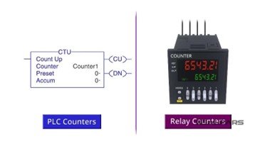
Counters in ladder Logic Programming Introduction: Counters in ladder logic programming are used to keep track of the number of occurrences of a specific event or condition. They count up or down based on predefined rules and control the sequence of operations in a control system. Counters are crucial for tasks that involve counting discrete events, managing process sequences, or implementing time-based operations. Types of Counters Up Counter (CTU – Count Up) Definition: Increments the count each time an input condition is true. Features: ▪ Counts upward from zero. ▪ Can be reset to zero with a reset input. Uses: ▪ Counting the number of products passing a checkpoint. ▪ Tracking the number of operations completed. Example: A packaging line where each product passing a sensor increases the count. Down Counter (CTD – Count Down) Definition: Decrements the count each time an input condition is true. Features: Starts from a preset value and counts down to zero. Can be reset to the preset value. Uses: Timing a process or controlling a countdown sequence. Managing inventory by counting down the number of items left. Example: A production process where a counter decreases each time a product is removed from stock. Up/Down Counter (CTUD – Count Up/Down) Definition: Allows counting in both directions based on control inputs. Features: Can count up or down based on control signals. Useful for applications requiring flexible counting operations. Uses: Counting items in and out of a bin. Managing complex processes that require bidirectional counting. Example: A warehouse system where items can be added or removed from inventory, and the counter adjusts accordingly. Features Preset Value: The target value for the counter to reach, which triggers an action or condition. Count Value: The current count of the counter. Increment/Decrement: Controls the direction of counting (up or down). Reset: Resets the counter to its initial state or a predefined value. Overflow: Some counters can handle overflow conditions if they exceed their maximum count. Uses Batch Counting: To manage production batches by counting the number of items processed. Timing Control: To measure elapsed time or control processes based on time intervals. Sequence Management: To control the sequence of operations in automated systems. Inventory Management: To keep track of the number of items in storage or production. Examples Example 1: Up Counter in a Packaging Line Scenario: You have a packaging line that needs to count each product as it moves past a sensor. Ladder Logic: CTU (Counter Up): Increments the count each time the sensor is triggered. Preset: Set to a target number of products. Output: An indicator light turns on when the count reaches the preset value. Example 2: Down Counter in a Production Process Scenario: You need to time a process that should last for a specific number of cycles. Ladder Logic: CTD (Counter Down): Starts from a preset value and decrements each time a process cycle completes. Reset: Resets the counter to the initial value at the start of a new cycle. Example 3: Up/Down Counter in Inventory Management Scenario: Managing a bin where items can be added or removed. Ladder Logic: CTUD (Up/Down Counter): Counts items added to the bin (increment) or removed from the bin (decrement). Control Inputs: Determine whether to count up or down based on the action. Counters are versatile tools in ladder logic programming that help automate and control processes by accurately tracking events and managing operations based on count values.  Example:Task 1 for counters (Write a code to turn ON a light after 6 events and turn it OFF after 10 seconds. Events may be treated as two normally open switches.)

Master Reset Ladder Logic Programming

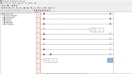
Master Reset Ladder Logic Programming Master Reset Function A Master Reset is used in ladder logic programming to reset all stored values in registers or memory locations to their default or initial state. It is often implemented to clear any previously stored data and prepare the system for a new operation or restart. Implementation in Ladder Logic In ladder logic, a Master Reset function can be represented by a simple rung that triggers a reset condition when a specific input or condition is met. Example Ladder Logic for Master Reset:

Magnetic Contactors and Relays

What are Magnetic Contactors and Relays? What is their role in the Automation industry? Magnetic Contactors Introduction Magnetic contactors and relays are essential components in the field of industrial automation. They play a crucial role in controlling electrical circuits, managing loads, and ensuring the safety and efficiency of automated systems. This report will explore the working principles, structure, types, and applications of magnetic contactors, as well as their significance in the automation industry. Magnetic Contactors Working Principle Magnetic contactors operate on the principle of electromagnetic attraction. When an electric current flows through the magnetic field coil located in the center leg of the coil core, it creates a magnetic field. This magnetic field generates a force that overcomes the spring force, causing the steel core to move down, closing the circuit. This state is referred to as the “ON” position. There are two sets of contactors that determine the operating condition: Normally Closed (NC) Contactor: Opens the contact point circuit when activated. Normally Open (NO) Contactor: Closes the contact point circuit when activated. When no current is flowing through the coil, the magnetic field dissipates, and the contactors return to their default states. Major Structure of Magnetic Contactors The basic elements of magnetic contactors are as follows: Iron Core: Divided into two parts: Fixed Core: Becomes an electromagnet when the coil is energized. Moving Core: Slides into the fixed core when the coil is energized, closing the circuit. Coil: The coil is powered to pull the main contacts close, with auxiliary contacts using the coil’s power to operate. Contacts: Magnetic contactors have two types of contacts: Main Contact: Used in the power circuit to connect the electrical system to the load. These contacts are designed to handle high current capacities. Auxiliary Contact: Used in the control circuit as secondary switching. These contacts can be normally open (NO) or normally closed (NC) and are designed for lower current capacities. Types of Magnetic Contactors Magnetic contactors are divided mainly into two categories: AC Contactors: Used with AC power, they are further classified based on their application: AC 1 Magnetic Contactor: Suitable for resistive loads with a power factor between 0.95 and 1, such as heaters and electrical furnaces. AC 2 Magnetic Contactor: Designed for slip-ring motors and high-torque applications. AC 3 Magnetic Contactor: Ideal for starting and stopping squirrel cage motors, used in elevators and lifts. AC 4 Magnetic Contactor: Suitable for frequent starting and stopping, used in cranes and other rapid start/stop applications. DC Contactors: Used with DC power, they are categorized as: DC-1 Magnetic Contactor: Suitable for inductive and slightly non-inductive loads like resistance furnaces. DC-2 Magnetic Contactor: Used for shunt motors and dynamic braking. DC-5 Magnetic Contactor: Designed for series motors and applications involving dynamic braking. Advantages of Magnetic Contactors Magnetic contactors offer several advantages over other switches: High Safety: They provide increased safety for operators. Ease of Control: They simplify the control of electrical circuits. Economical: They are cost-effective compared to manual controls. Remote Control: Magnetic contactors can be controlled automatically or remotely, enhancing operational flexibility. Applications of Magnetic Contactors Magnetic contactors are widely used in various applications, including: Magnetic Motor Starters: These are electrically operated switches that include motor overload protection. They are similar to contactors but with added overload relays to protect motors from excessive current flow. Lighting Control Contactors: Used for remote or local switching of large lighting loads, such as mercury, fluorescent, tungsten, or LED lights. They enable centralized ON/OFF control of lighting systems.

PLC Programming Function Block Diagrams

PLC Programming Function Block Diagrams What Are Function Block Diagrams? An FBD (function block diagram) program is a graphical programming language that joins functions together to produce an output. Using lines and flags to represent variables in a more graphical format, the user can quickly build a program by dragging, dropping, and connecting different function blocks and variables. In the end, the program looks similar to logical block diagrams that might have been used to describe complex processes in school or during the design phase of equipment. By using a graphical programming language, the user can quickly produce programs using proven, debugged, code which reduces integration time and results in less wasted product. Users do not need an extensive programming or electrical background to develop FBD programs. What are Function Blocks? A function block can be written in any IEC-supported language, parameters (inputs) are passed into the function block, some logic is performed on the parameters, output variables are set or data is passed out of the block. Function blocks can contain small amounts of code or larger sections of code. The intent of a function block is to reduce the amount of repeated code. This is accomplished by using the input parameters writing the code to be dynamic then setting the output parameters. A simple FBD example would be triggering a camera. Many handshakes are required to ensure the picture has been taken and the results will need to be copied to a useful datatype. The function block may only need one input to start the acquisition and two outputs, one being an error flag, and the other being the results of the inspection. This same block can be used for each camera in the system. When debugging you would only need to debug one section of code. FBD Program Execution FBD program execution is dependent on the functions that are being called. If for example, you are calling a custom function that has many internal processes and in parallel you are also calling a simple function the parallel process will execute faster to the second function. This can cause some confusion. It is important to note that functions can run in parallel but will execute at different rates. Program execution is typical from left to right, but can go up and down depending on the placement of function blocks. When Should I Use FBDs? Many die-hard PLC programmers will swear by ladder logic or structured text programs, but there are occasions when an FBD program could result in a faster more responsive system. Process automation works well with FBDs because block diagrams are used to design and explain their process when data is shared between events and other processes. One step can only advance once an input process has been completed, this is different from a sequence where boolean sensors or events are used to determine the end of a sequence. Think of baking cookies, you need to gather ingredients, prep ingredients, bake, package, and ship the cookies. The output of one function directly affects the next function and some functions like bake might have two inputs, cookies, and pre-heat oven for example. Safety systems are commonly using FBD programs because it is simple and quick to read. Complex safety programs leave room for errors, and mistakes within a safety program could cost human lives or injuries. Situations with repetitive code within a program can benefit from FBD programs by simply dragging, dropping, and assigning a user can build a program with proven functions very quickly. This can reduce training and the requirement for advanced-level programmers on the shop floor. Collaborative robots are making use of FBDs for this specific reason. Multiple PID loops work well in FBDs because of their parallel processing abilities. While other programming languages also have parallel processing capabilities, it’s easier to follow multiple processes in an FBD program. How To Use FBDs When building a program using the FBD language you want to make sure your program is fairly simple. Even though FBD programs are easy to read and debug they can be made very complex with many functions connected together. Try to spread out your functions as much as you can. When functions are bunched together it is hard to tell where the lines are coming from and where they are going. Reduce the number of branched outputs, some programming environments will only allow for so many outputs, if any, to be connected together. Keep the number of output connections to no more than three. This reduces complexity and will keep your diagram less cluttered.

TCP/IP and IP Configuration in PLCs

Architecture of using IQ Home Gateway Modbus TCP/IP interface using PLC applications This document describes how to connect to IQ Home Gateway Modbus TCP interface. IQ Home Gateway Modbus TCP interface provides a solution to access Modbus Slave devices with IQ Home MB Series (MB-XXX-XX) products and read periodically collected battery powered sensor values as virtual devices. Figure : Architecture of using IQ Home Gateway Modbus TCP/IP interface using PLC applications TCP/IP and IP Configuration in PLCs Introduction TCP/IP (Transmission Control Protocol/Internet Protocol) is a set of communication protocols used for interconnecting network devices on the internet. In the context of PLCs (Programmable Logic Controllers), TCP/IP enables communication between PLCs and other devices, such as computers, sensors, and actuators, within an industrial network. What is TCP/IP? TCP/IP Protocol Suite: TCP/IP is a suite of communication protocols used to connect devices on the internet and local networks. It includes various protocols, with the main ones being TCP (Transmission Control Protocol) and IP (Internet Protocol). TCP (Transmission Control Protocol): TCP ensures reliable, ordered, and error-checked delivery of data between applications running on networked devices. It establishes a connection between the sender and receiver before transmitting data and ensures data integrity. IP (Internet Protocol): IP is responsible for addressing and routing packets of data so they can travel across networks and arrive at the correct destination. IP addresses uniquely identify devices on a network. How TCP/IP is Used in PLCs 1. Communication: TCP/IP enables PLCs to communicate with other devices and systems, allowing for data exchange and remote control. This communication is essential for monitoring and controlling industrial processes in real-time. 2. SCADA Systems: Supervisory Control and Data Acquisition (SCADA) systems use TCP/IP to communicate with PLCs for monitoring and controlling industrial processes. SCADA systems collect data from PLCs and provide operators with a comprehensive view of the system’s status.   3. Remote Access: TCP/IP allows for remote access to PLCs, enabling technicians to diagnose and troubleshoot issues from a remote location. This capability improves maintenance efficiency and reduces downtime. What is IP Configuration? 1. IP Address: An IP address is a unique identifier assigned to each device on a network. It consists of four octets separated by dots (e.g., 192.168.1.1). 2. Subnet Mask: The subnet mask defines the network and host portions of an IP address. It is used to divide an IP address into subnets and manage network traffic. 3. Default Gateway: The default gateway is the device that routes traffic from a local network to other networks, including the internet. It serves as an access point for devices to communicate outside their local network. How IP Configuration is Used in PLCs 1. Network Setup: Proper IP configuration is essential for setting up a network of PLCs and other devices. Each PLC must have a unique IP address within the network to avoid conflicts. 2. Communication with Devices: IP configuration enables PLCs to communicate with other devices, such as sensors, actuators, and HMI (Human-Machine Interface) panels. This communication is crucial for coordinating and controlling industrial processes. 3. Integration with SCADA Systems: IP configuration allows PLCs to integrate with SCADA systems, providing real-time data and control capabilities. Proper IP configuration ensures seamless communication between the SCADA system and PLCs. Example Multi-level Networks with IP Address: PLC 1 with IP Address 192.168.111.1 PLC 2 with IP Address 192.168.111.2 PLC 3 with IP Address 192.168.111.3

Sensor and Actuators

Sensor and Actuators What is a sensor? A sensor is a device that senses something. Today we have sensors that can see, feel, hear, smell, and even taste. Without sensors, our home and work lives would be quite difficult. For example, as you drive to work, the traffic lights at an intersection are controlled by sensors embedded in the road. These sensors detect your arrival at the intersection. As you approach the grocery store, the door automatically opens because of a sensor. In your plant, the batch process temperature and pressure are displayed and controlled as a result of output from Sensors. Industrial sensors In the world of instrumentation and process control, we define a Sensor as a device that detects changes in physical, electrical, or chemical properties and produces an electrical output in response to that change. Types of sensors What are the typical physical properties that sensors are detecting? Let’s name a few… Level, Temperature, Flow, Pressure, Speed, and Position. Classification of sensors From a process control perspective, we can classify sensors as either Passive or Active. Passive sensors A Passive Sensor requires an external source of power to operate while an Active Sensor does not. Active sensors A Thermocouple is an Active Sensor as it does not require any external power supply to operate. Active sensors examples As a thermocouple is exposed to an increase in temperature, it will develop an increasing voltage across it. Another example of an Active sensor is a piezoelectric sensor. Passive sensors examples A Resistance Temperature Detector (RTD) is a Passive Sensor. It is a device that’s resistance will change with a change in temperature. To take advantage of this change in resistance, an external supply, or an excitation circuit is required to produce a change in voltage. Another example of a Passive sensor is a Strain Gauge. Sensors in the industry Alright now that we’ve talked about different sensor types and the physical properties that they can sense, let’s discuss how they are used in the industry. Almost every sensor used in process control will be connected to a Transmitter because a sensor’s output needs to be conditioned or amplified. Here’s an example…We’ve already talked about a thermocouple and the voltage output created when it is heated. Unfortunately, the voltage output of a thermocouple is minuscule! In our example, the thermocouple will produce a voltage output from 8 mV to 18 mV over a 450 degree Fahrenheit change in temperature! In-process control, we condition that 8mV to 18mV thermocouple voltage and convert it to a 4 mA to 20 mA industry-standard signal that represents our controlled temperature range. What is actuator? An actuator is a device that makes something move or operate. Every one of us takes advantage of at least one actuator every day. Let’s look at some examples of actuators. Grocery Store Door When we go to the grocery store, the door opens automatically for us. An actuator makes the door open. Car Seat We can move the car seat forward or backward before we drive away in our car. An actuator makes the seat move. Types of Actuators Linear Actuator An actuator can move something in a straight line, also referred to as linear. Rotary Actuator An actuator can make something move in a circular motion, also referred to as rotary. What Makes an Actuator Move? We’ve talked about the movement of an actuator, but we haven’t discussed how, or what makes it move. Actuators receive a source of energy and use it to move something. To put it another way, the actuator converts a source of energy into a physical-mechanical motion. A butterfly valve is operated by turning the Handwheel connected to the rotary actuator. In industrial applications, the Handwheel could be replaced by one of three typical sources of energy, which can operate the rotary actuator: – Electric actuators use some form of electric energy to operate. – Hydraulic actuators use a variety of liquids as a source of energy. – Pneumatic actuators are operated by compressed air. Types of Actuators Typical actuator types in the industry include: – Electric Motors – Hydraulic motors – Pneumatic Control Valves 4-20 mA Pneumatic Actuator Let’s look at a typical Pneumatic Actuator in action! The PLC analog output card produces a 4-20 mA current to move the valve from fully open to fully closed. The 4-20 mA current will be converted to pneumatic pressure which becomes the source of energy to operate the actuator. Electrical Drive The system which is used for controlling the motion of an electrical machine, such type of system is called an electrical drive. In other words, the drive which uses the electric motor is called electrical drive. The electrical drive uses any of the prime movers like diesel or a petrol engine, gas or steam turbines, steam engines, hydraulic motors and electrical motors as a primary source of energy. This prime mover supplies the mechanical energy to the drive for motion control. The block diagram of the electrical drive is shown in the figure below. The electrical load like fans, pumps, trains, etc., consists the electrical motor. The requirement of an electrical load is determined regarding speed and torque. The motor which suited the capabilities of the load is chosen for the load drive. Parts of Electrical Drive: The main parts of the electrical drives are power modulator, motor, controlling unit and sensing units.Their parts are explained below in details. Power Modulator: The power modulator regulates the output power of the source. It controls the power from the source to the motor in such a manner that motor transmits the speed-torque characteristic required by the load. During the transient operations like starting, braking and speed reversing the excessive current drawn from the source. This excessive current drawn from the source may overload it or may cause a voltage drop. Hence the power modulator restricts the source and motor current. The power modulator converts the energy according to the requirement of the motor e.g. if the source is DC and an induction motor is used then power modulator convert DC into AC. It also selects the

What is actuator?

What is actuator? An actuator is a device that makes something move or operate. Every one of us takes advantage of at least one actuator every day. Let’s look at some examples of actuators. Grocery Store Door When we go to the grocery store, the door opens automatically for us. An actuator makes the door open. Car Seat We can move the car seat forward or backward before we drive away in our car. An actuator makes the seat move. Types of Actuators Linear Actuator An actuator can move something in a straight line, also referred to as linear. Rotary Actuator An actuator can make something move in a circular motion, also referred to as rotary. What Makes an Actuator Move? We’ve talked about the movement of an actuator, but we haven’t discussed how, or what makes it move. Actuators receive a source of energy and use it to move something. To put it another way, the actuator converts a source of energy into a physical-mechanical motion. A butterfly valve is operated by turning the Handwheel connected to the rotary actuator. In industrial applications, the Handwheel could be replaced by one of three typical sources of energy, which can operate the rotary actuator: – Electric actuators use some form of electric energy to operate. – Hydraulic actuators use a variety of liquids as a source of energy. – Pneumatic actuators are operated by compressed air. Types of Actuators Typical actuator types in the industry include: – Electric Motors – Hydraulic motors – Pneumatic Control Valves 4-20 mA Pneumatic Actuator Let’s look at a typical Pneumatic Actuator in action! The PLC analog output card produces a 4-20 mA current to move the valve from fully open to fully closed. The 4-20 mA current will be converted to pneumatic pressure which becomes the source of energy to operate the actuator. Electrical Drive The system which is used for controlling the motion of an electrical machine, such type of system is called an electrical drive. In other words, the drive which uses the electric motor is called electrical drive. The electrical drive uses any of the prime movers like diesel or a petrol engine, gas or steam turbines, steam engines, hydraulic motors and electrical motors as a primary source of energy. This prime mover supplies the mechanical energy to the drive for motion control. The block diagram of the electrical drive is shown in the figure below. The electrical load like fans, pumps, trains, etc., consists the electrical motor. The requirement of an electrical load is determined regarding speed and torque. The motor which suited the capabilities of the load is chosen for the load drive. Parts of Electrical Drive: The main parts of the electrical drives are power modulator, motor, controlling unit and sensing units.Their parts are explained below in details. Power Modulator: The power modulator regulates the output power of the source. It controls the power from the source to the motor in such a manner that motor transmits the speed-torque characteristic required by the load. During the transient operations like starting, braking and speed reversing the excessive current drawn from the source. This excessive current drawn from the source may overload it or may cause a voltage drop. Hence the power modulator restricts the source and motor current. The power modulator converts the energy according to the requirement of the motor e.g. if the source is DC and an induction motor is used then power modulator convert DC into AC. It also selects the mode of operation of the motor, i.e., motoring or braking. Control Unit : The control unit controls the power modulator which operates at small voltage and power levels. The control unit also operates the power modulator as desired. It also generates the commands for the protection of power modulator and motor. An input command signal which adjusts the operating point of the drive, from an input to the control unit. Sensing Unit : It senses the certain drive parameter like motor current and speed. It mainly required either for protection or for closed loop operation. Advantages of Electrical Drive The following are the advantages of electrical drive. The electric drive has very large range of torque, speed and power. Their working is independent of the environmental condition. The electric drives are free from pollution. The electric drives operate on all the quadrants of speed torque plane. The drive can easily be started and it does not require any refuelling. The efficiency of the drives is high because fewer losses occur on it. The electric drives have many advantages shown above. The only disadvantage of the drive is that sometimes the mechanical energy produced by the prime mover is first converted into electrical energy and then into a mechanical work by the help of the motor. This can be done by the help of the electrical link which is associated with the prime mover and the load. Because of the following advantages, the mechanical energy already available from a non-electrical prime mover is sometimes first converted into electrical energy by a generator and back to a mechanical energy of an electrical motor. Electrical link thus provides between the non-electrical prime mover and the load impact to the drive flexible control characteristic. For example – The diesel locomotive produces the diesel energy by the help of the diesel engine. The mechanical energy is converted into an electrical energy by the help of the generator. This electrical energy is used for driving the other locomotive. Disadvantages of Electrical Drive: The power failure completely disabled the whole of the system. The application of the drive is limited because it cannot use in a place where the power supply is not available. It can cause noise pollution. The initial cost of the system is high. It has a poor dynamic response. The output power obtained from the drive is low. During the breakdown of conductors or short circuit, the system may get damaged due to which several problems occur. Application of Electric Drive It is used in a large number of industrial and domestic applications like transportation systems, rolling mills,