Author name: Kamran Khan

What Is Modbus

What is Modbus

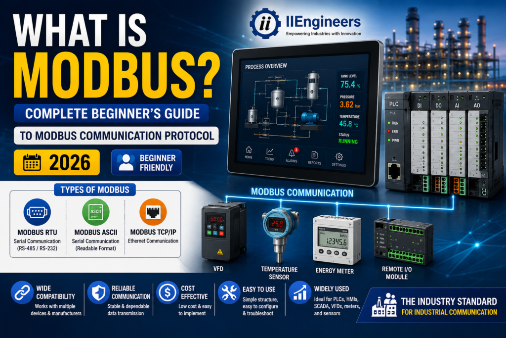
What is Modbus? Complete Beginner’s Guide to Modbus Communication Protocol (2026)   What is Modbus? Industrial automation relies on seamless communication between machines, controllers, sensors, and monitoring systems. One of the oldest and most trusted communication protocols in this field is Modbus. Even after more than four decades, Modbus remains one of the most widely used industrial communication protocols because of its simplicity, reliability, and compatibility with equipment from different manufacturers. Whether you are learning PLC programming, working with SCADA systems, integrating sensors, or designing automation networks, understanding Modbus is an essential skill. It enables different industrial devices to exchange data efficiently, making it easier to build reliable and scalable automation systems. In this guide, you’ll learn what Modbus is, how it works, its different types, communication methods, message structure, applications, advantages, and why it continues to be one of the most popular protocols in industrial automation. What Is Modbus? Modbus is an industrial communication protocol developed by Modicon in 1979 for communication with Programmable Logic Controllers (PLCs). Today, Modicon is part of Schneider Electric, while the ongoing development and maintenance of the protocol are managed by the Modbus Organization, an association dedicated to ensuring compatibility between Modbus-compliant devices. Modbus provides a common communication language that allows industrial equipment from different manufacturers to exchange information. Instead of relying on proprietary protocols, automation devices can communicate using a standardized format, making system integration much easier. For example, a temperature sensor, humidity sensor, PLC, HMI, and SCADA system can all exchange data using Modbus, allowing operators to monitor and control industrial processes from a central location. Why Is Modbus Important? Modern industrial plants often use equipment from multiple manufacturers. Without a common communication protocol, integrating these devices would be difficult and expensive. Modbus solves this challenge by providing a universal method for communication. Automation engineers use Modbus because it offers: Easy integration between different devices Reliable industrial communication Low implementation cost Simple configuration and troubleshooting Compatibility with PLCs, HMIs, SCADA systems, VFDs, energy meters, and sensors Wide industry acceptance Because of these advantages, Modbus has become one of the most in-demand skills for industrial automation engineers. How Does Modbus Work? Modbus follows a client-server architecture in Ethernet-based networks and a master-slave architecture in serial communication. In a traditional serial Modbus network: The Master device initiates all communication. The Slave device responds to requests from the master. Slave devices cannot communicate unless requested by the master. For example, a PLC acting as the master may request temperature values from a remote temperature transmitter configured as Slave Address 01. The sensor processes the request and sends the requested data back to the PLC. This simple communication model makes Modbus highly reliable and predictable. Types of Modbus Different industrial applications require different communication methods. Modbus is available in three primary versions. Modbus RTU (Remote Terminal Unit) Modbus RTU is the most commonly used version in industrial automation. It communicates over serial interfaces such as RS-232 or RS-485 and represents data in binary format, making communication compact and efficient. Key Features Serial communication Binary data format Fast and efficient transmission Excellent for real-time applications Most widely used in PLC-based automation Common Applications PLC communication Variable Frequency Drives (VFDs) Energy meters Remote I/O systems Industrial sensors Modbus ASCII Modbus ASCII also uses serial communication but transmits information using readable ASCII characters. Although easier to troubleshoot manually, it is slower and less efficient than Modbus RTU because each byte is transmitted as two ASCII characters. Key Features Serial communication Human-readable messages Easier manual debugging Lower communication efficiency Typical Applications Legacy automation systems Diagnostic applications Educational environments Modbus TCP/IP Modbus TCP/IP combines the Modbus protocol with Ethernet networking. Instead of transmitting messages directly over serial cables, Modbus data is encapsulated inside TCP/IP packets. This allows Modbus devices to communicate over modern Ethernet networks while maintaining compatibility with traditional Modbus commands. Key Features Ethernet communication High-speed data transfer Supports large networks Easy integration with SCADA systems Compatible with Industrial Ethernet infrastructure Typical Applications Smart factories Industrial IoT SCADA systems Building management systems Process automation Comparison of Modbus Types Feature Modbus RTU Modbus ASCII Modbus TCP/IP Communication RS-232 / RS-485 RS-232 / RS-485 Ethernet Data Format Binary ASCII TCP/IP Packets Speed High Moderate Very High Efficiency Excellent Lower Excellent Human Readability No Yes No Typical Applications PLC Networks Diagnostics Industrial Ethernet Physical Communication Media The original Modbus implementation operated over RS-232 serial communication. However, most modern industrial systems use RS-485 because it provides significant advantages. RS-485 Advantages Longer communication distances Higher communication speeds Multiple devices on one network Better noise immunity Lower installation cost These benefits make RS-485 the preferred physical layer for Modbus RTU installations. For larger industrial networks, Modbus TCP/IP operates over standard Ethernet infrastructure, allowing communication between controllers, HMIs, servers, and SCADA systems. Number of Devices Supported Modbus RTU and ASCII A single Modbus serial network can theoretically support 247 slave devices, although practical limits depend on cable length, signal quality, baud rate, and network design. Modbus TCP/IP Modbus TCP/IP supports a virtually unlimited number of devices, with the actual limit determined by the Ethernet network infrastructure, switches, routers, and IP addressing. This scalability makes Modbus TCP/IP ideal for large industrial facilities. Communication Speed (Baud Rate) For Modbus RTU and ASCII, common baud rates include: 1200 bps 2400 bps 4800 bps 9600 bps 19200 bps 38400 bps 57600 bps 115200 bps Higher baud rates increase communication speed but require better cable quality and shorter communication distances. For Modbus TCP/IP, communication speed depends on the Ethernet network. Typical Ethernet speeds include: 10 Mbps 100 Mbps 1 Gbps Modbus Data Flow A complete Modbus communication cycle follows a simple sequence. Step 1 – Request The master sends a request to a specific slave device. The request includes: Slave Address Function Code Register Address Data or Quantity Error Checking Information Step 2 – Processing The slave receives the request, checks its validity, processes the requested action, and prepares a response. Step 3 – Response The slave returns the requested information
HMI System and DCS system

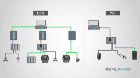
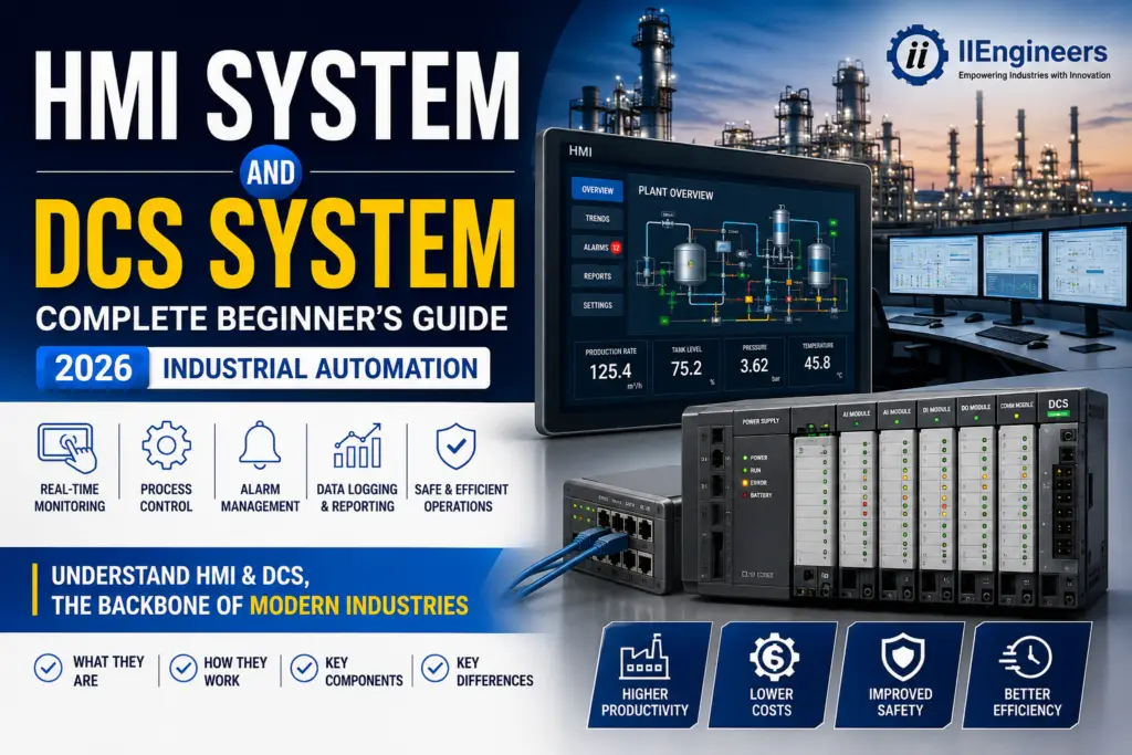
HMI System and DCS System Industrial automation has transformed the way modern industries operate. From manufacturing plants to power stations, automation systems improve productivity, enhance safety, and reduce operational costs. Among the most important technologies used in industrial automation are the Human-Machine Interface (HMI) and the Distributed Control System (DCS). Although HMI and DCS often work together, they serve different purposes. An HMI allows operators to monitor and control industrial processes through a graphical interface, while a DCS manages and controls complex industrial operations through multiple distributed controllers. In this guide, we’ll explain everything you need to know about HMI and DCS systems, including their components, functions, applications, benefits, and differences. What Is an HMI System? A Human-Machine Interface (HMI) is a software and hardware solution that enables communication between people and industrial machines. It provides operators with a visual interface where they can monitor machine performance, view process data, receive alarms, and control equipment. Instead of manually checking each machine, operators can monitor the entire production process from a single screen. Modern HMIs are typically displayed on industrial touch panels, computers, or operator stations and are designed to simplify industrial operations. Why Is an HMI Important? Without an HMI, operators would have to rely on individual switches, indicator lights, and manual inspections to manage industrial equipment. An HMI centralizes all important information, making operations faster, safer, and more efficient. HMIs help operators: Monitor real-time production data Start and stop machines Adjust process parameters View system alarms Analyze historical production data Improve production efficiency Reduce machine downtime Key Components of an HMI System Display Interface The display interface is the most visible part of an HMI. It presents real-time information using graphics, charts, trends, gauges, and process animations. Modern HMIs use high-resolution touchscreen displays that are easy to operate. Control Interface Operators use the control interface to interact with machinery. From this screen, they can start motors, open valves, adjust production settings, or reset alarms. Communication Interface An HMI communicates with industrial devices such as PLCs, sensors, drives, and controllers using communication protocols including: Ethernet/IP Modbus Profinet Profibus OPC UA MQTT These communication networks allow the HMI to display live process information. Main Functions of an HMI Real-Time Monitoring Operators can monitor machine status, production levels, temperatures, pressures, flow rates, motor speeds, and other critical process values in real time. Process Control HMIs allow users to control industrial equipment directly from the graphical interface. Operators can start production, stop machines, change recipes, or adjust operating parameters. Alarm Management When abnormal conditions occur, such as high temperature or low pressure, the HMI immediately displays alarms. This enables operators to respond quickly and prevent equipment damage. Data Logging and Reporting Most modern HMIs record production data, machine events, alarms, and operating history. These reports help maintenance teams identify recurring problems and improve production efficiency. Benefits of HMI Systems An HMI offers numerous advantages for industrial facilities. Easy-to-use graphical interface Faster operator response Improved production monitoring Better decision-making through real-time data Reduced machine downtime Improved process visibility Increased operational efficiency Better maintenance planning Enhanced workplace safety Common Applications of HMI HMI systems are used in almost every industrial sector, including: Manufacturing Food and beverage processing Pharmaceutical plants Oil and gas facilities Water treatment plants Chemical industries Power generation Building automation Packaging systems Mining operations What Is a DCS System? A Distributed Control System (DCS) is an advanced industrial automation system designed to control large and complex industrial processes. Instead of using one central controller, a DCS distributes control across multiple controllers installed throughout the plant. Each controller is responsible for a specific section of the process, while all controllers communicate through a high-speed industrial network. Operators can monitor and control the complete plant from centralized HMI workstations. How Does a DCS Work? A DCS continuously collects information from sensors installed throughout the plant. Each controller processes the data independently and sends commands to field devices such as valves, pumps, motors, and actuators. The results are displayed on HMI operator stations, allowing engineers to monitor the entire process in real time. Because control is distributed, the failure of one controller usually affects only a small portion of the plant rather than the entire operation. Main Components of a DCS Distributed Controllers Controllers perform control calculations, execute automation logic, and manage process operations for individual plant sections. Field Devices Field devices include: Temperature transmitters Pressure transmitters Flow meters Level sensors Control valves Motors Pumps Actuators These devices collect process data and execute control commands. Human-Machine Interface (HMI) The HMI provides operators with a complete overview of the plant. Through the HMI, users can monitor production, adjust process parameters, acknowledge alarms, and review historical trends. Communication Network The communication network connects controllers, HMIs, servers, and field devices using industrial communication protocols such as: Ethernet Foundation Fieldbus Profibus Profinet Modbus TCP/IP Reliable communication is essential for maintaining plant stability. Key Features of a DCS Distributed Control Each controller independently manages its assigned process area, improving system reliability. Scalability A DCS can easily expand as new production lines or plant sections are added. High Reliability Most DCS systems include redundant controllers, servers, communication networks, and power supplies, ensuring continuous operation even during equipment failures. System Integration Modern DCS platforms integrate with PLCs, SCADA systems, historians, MES software, ERP systems, and Industrial Internet of Things (IIoT) platforms. Benefits of a DCS System Industries choose DCS systems because they provide: Superior process control Improved product quality High system availability Reduced downtime Enhanced plant safety Centralized monitoring Flexible expansion Easier maintenance Better process optimization Industries That Use DCS DCS systems are commonly found in industries where continuous production is critical. These include: Oil and gas Petrochemical plants Chemical processing Power generation Water and wastewater treatment Cement manufacturing Paper mills Pharmaceutical production Steel manufacturing Food processing HMI vs DCS: What’s the Difference? Although HMI and DCS work together, they perform different functions. Feature HMI DCS Primary Purpose Operator Interface Process Control System Main Function Monitoring and Control Distributed Process Automation User

What Is PLC? Complete Beginner’s Guide (2026)

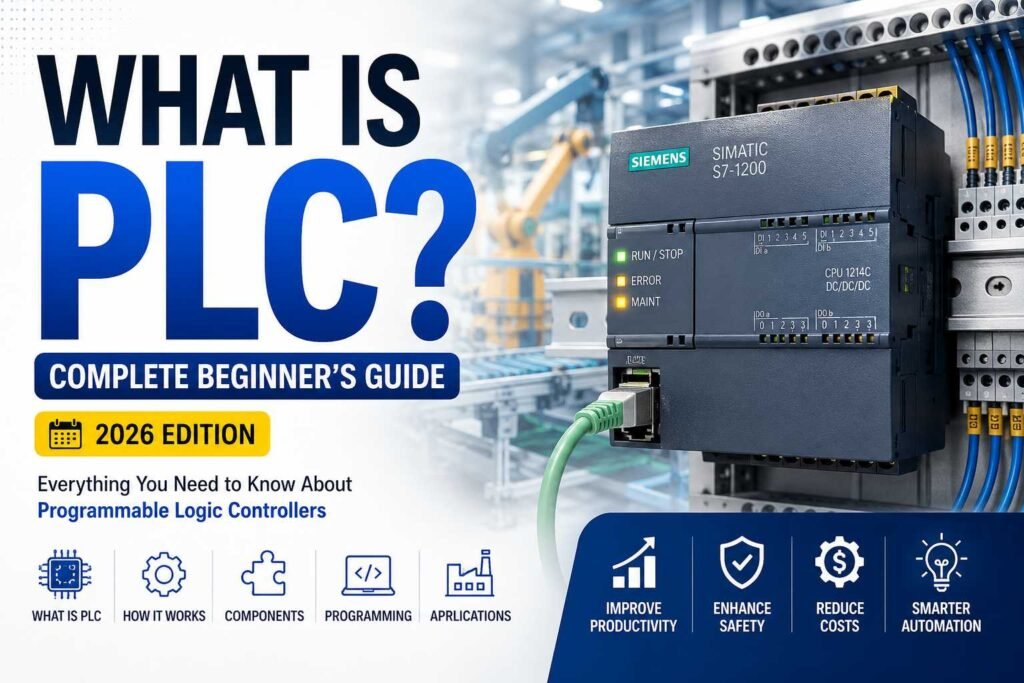
What Is PLC? If you’ve ever wondered how factories automatically fill bottles, package food, control conveyor belts, or manage massive industrial plants without constant human intervention, the answer often comes down to one powerful device: the Programmable Logic Controller (PLC). In today’s era of smart manufacturing and Industry 4.0, PLCs have become the backbone of industrial automation. From small manufacturing units to large oil refineries, almost every automated process relies on PLC technology to ensure speed, reliability, precision, and safety. Whether you’re an engineering student, an electrician, a technician, or someone planning a career in industrial automation, understanding PLCs is one of the most valuable skills you can develop. This complete beginner’s guide explains everything you need to know about PLCs in simple language. By the end of this article, you’ll understand what a PLC is, how it works, where it’s used, how to learn PLC programming, and why PLC skills remain in high demand in 2026. What Does PLC Stand For? PLC stands for Programmable Logic Controller. A PLC is a rugged industrial computer specifically designed to automate machines and industrial processes. Unlike a regular computer, a PLC is built to operate continuously in harsh industrial environments where dust, vibration, heat, moisture, and electrical noise are common. Instead of manually switching motors, valves, pumps, or conveyors on and off, a PLC automatically performs these operations based on the logic programmed into it. Think of a PLC as the “brain” of an automated machine. It continuously receives information from sensors, processes that information according to the programmed logic, and then sends commands to control devices like motors, relays, solenoid valves, alarms, and actuators. Why Are PLCs So Important? Before PLCs were invented, industries relied on thousands of relays and timers connected through complicated wiring. Whenever production requirements changed, technicians had to rewire entire control panels. This process was expensive, slow, and prone to errors. PLCs revolutionized industrial automation because changing machine behavior became as simple as updating software instead of rewiring electrical panels. Today, PLCs help industries: Increase production speed Reduce machine downtime Improve product quality Lower maintenance costs Enhance worker safety Save energy Improve process reliability This flexibility has made PLCs an essential part of modern manufacturing. History of PLC The first PLC was introduced in 1968 by Dick Morley. The automotive industry needed a better alternative to relay-based control systems because changing production lines required massive rewiring efforts. The first commercially successful PLC was developed by Modicon. Since then, PLC technology has evolved dramatically. Modern PLCs now support: Ethernet communication Remote monitoring Cloud connectivity Industrial IoT Data logging Artificial Intelligence integration Predictive maintenance This evolution continues to drive smarter factories around the world. How Does a PLC Work? A PLC operates using a continuous cycle known as the Scan Cycle. The scan cycle consists of four main steps. Step 1: Read Inputs The PLC first checks all connected input devices. Examples include: Push buttons Limit switches Temperature sensors Pressure transmitters Proximity sensors Float switches Emergency stop buttons The PLC reads their current status. Step 2: Execute Program Next, the PLC executes the user program stored in its memory. This program contains all the logic created by the programmer. It determines how the machine should respond to different conditions. Step 3: Update Outputs After processing the logic, the PLC updates its outputs. Outputs may include: Motors Contactors Valves Indicator lights Buzzers Hydraulic systems Pneumatic cylinders Step 4: Repeat The PLC repeats this entire process continuously. Most PLCs complete one scan in only a few milliseconds. This incredibly fast response allows industrial systems to operate safely and efficiently. Main Components of a PLC Understanding PLC hardware is important before learning programming. CPU (Central Processing Unit) The CPU is the brain of the PLC. It processes input signals, executes logic, performs calculations, and controls outputs. Power Supply The power supply converts incoming electrical power into the voltage required by the PLC. Input Modules Input modules receive signals from sensors and field devices. Examples include: Digital inputs Analog inputs Temperature inputs Pulse inputs Output Modules Output modules send signals to field devices. Examples include: Relay outputs Transistor outputs Triac outputs Analog outputs Memory Memory stores: User programs Configuration Timers Counters Internal variables Communication Ports Communication ports allow PLCs to communicate with: HMIs SCADA systems VFDs Remote I/O Other PLCs Industrial networks Types of PLC   Compact PLC Compact PLCs integrate CPU, power supply, and I/O into one unit. They are suitable for small automation projects. Modular PLC Modular PLCs allow expansion by adding extra modules. These are commonly used in medium and large industries. Rack PLC Rack PLCs support hundreds or thousands of input and output points. They are used in: Power plants Oil and gas Steel industries Water treatment plants Safety PLC Safety PLCs are designed for critical applications where human safety is essential. Examples include emergency shutdown systems and machine safety circuits. PLC Inputs Explained Inputs provide information about the process. Common digital inputs include: Push buttons Selector switches Emergency stops Limit switches Photoelectric sensors Common analog inputs include: Temperature transmitters Pressure sensors Flow transmitters Level transmitters pH sensors PLC Outputs Explained Outputs perform the actual work. Examples include: Motors Pumps Contactors Solenoid valves Alarm sirens Tower lights Conveyor belts PLC Programming Languages The IEC 61131-3 standard defines several programming languages. Ladder Logic (LD) The most popular PLC programming language. It resembles electrical relay diagrams and is beginner-friendly. Function Block Diagram (FBD) Uses interconnected function blocks. Ideal for analog control systems. Structured Text (ST) A high-level programming language similar to Pascal. Useful for complex calculations. Sequential Function Chart (SFC) Used for sequential operations. Common in batch processing. Instruction List (IL) Older programming language. Rarely used in modern PLCs. Popular PLC Manufacturers Some of the world’s leading PLC manufacturers include: Siemens Allen-Bradley (Rockwell Automation) Mitsubishi Electric Omron Schneider Electric ABB Delta Keyence Beckhoff Phoenix Contact Each platform has its own programming software and hardware architecture. Where Are PLCs Used? PLCs are found in nearly every modern industry. Manufacturing Automated assembly

The Backbone of Industrial Automation: PLCs, HMIs, SCADA & DCS

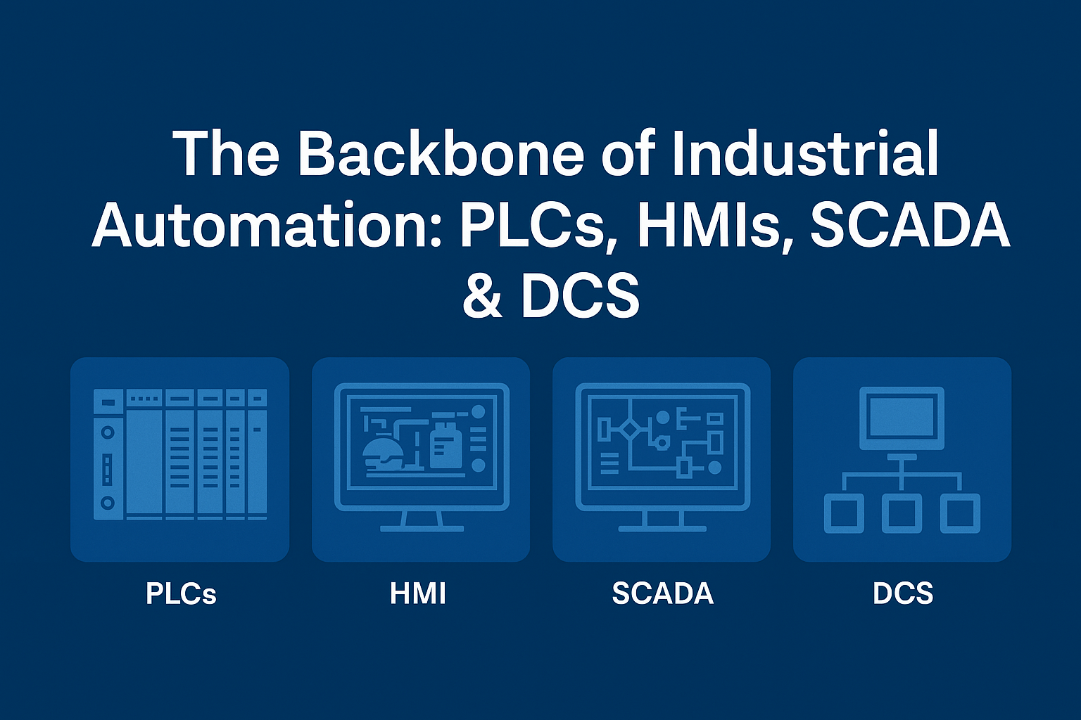
The Backbone of Industrial Automation PLCs, HMIs, SCADA & DCS In today’s fast-paced manufacturing world, automation isn’t a luxury; it’s the standard. At the core of every smart factory and production line, you’ll find one common denominator: Programmable Logic Controllers (PLCs). Whether you’re an aspiring automation engineer or a seasoned professional looking to upgrade your skills, understanding how PLCs, Human Machine Interfaces (HMIs), SCADA, and DCS systems work together is essential.   Programmable Logic Controllers (PLCs): A PLC is a rugged digital computer designed for the harsh conditions of industrial environments. Used to control machinery, monitor inputs and outputs, and automate complex sequences, Programmable Logic Controllers are the brains behind most industrial processes. From packaging lines and bottling plants to chemical reactors and HVAC systems, PLCs are everywhere. Their ability to execute ladder logic, process real-time data, and run continuously without fail makes them indispensable. Popular models include: • Siemens PLC – Known for reliability and global industry standard. • Fatek PLC – A cost-effective and compact solution, popular in Asia. • Mitsubishi PLC – Widely used in high-speed and precise motion control. • Delta PLC – Offers flexible and affordable automation options for small to mid-sized operations. Each PLC brand has its strengths, and selecting the right one depends on your application, scalability needs, and integration ecosystem. HMI: Bridging Humans and Machines: The Human Machine Interface (HMI) is where operators interact with the automated system. Think of it as the dashboard of your car, only for your entire factory. An HMI displays real-time process data, alarms, and control buttons that let technicians tweak the system on the fly. A popular and affordable HMI brand, especially in small and mid-sized industries, is Weintek HMI. These touch-based panels are intuitive, durable, and easily integrate with most major PLCs, including Siemens, Delta, and Fatek. Without HMIs, the world of industrial automation would be a black box, with no feedback, no status, and no real control. HMIs make the invisible visible. The Role of SCADA – Your System’s Nervous System: While PLCs act as the brain and HMIs as the face, the Secondary Control and Data Acquisition System, more commonly referred to as SCADA, serves as the nervous system. SCADA enables centralized control and monitoring across multiple devices, lines, or even geographical sites. Here’s what SCADA systems do: • Collect real-time data from multiple PLCs • Generate trends and reports • Send alerts and alarms • Allow remote supervision and control For instance, in a water treatment facility, SCADA may gather data from hundreds of pumps and valves controlled by Siemens PLCs and display system-wide health on a Weintek HMI. That’s the power of SCADA—macro-level visibility with micro-level control. Distributed Control System (DCS) – Managing Complex Processes: When it comes to process-heavy industries like oil & gas, power plants, and pharmaceutical manufacturing, Distributive Control Systems (DCS) shine. A DCS is similar to a SCADA system but better suited for continuous, complex processes. While PLCs are great for discrete manufacturing (like packaging), DCS handles continuous operations with thousands of process variables. Some key differences: • DCS has integrated control and data acquisition, whereas SCADA often uses separate systems. • DCS is more process-oriented, while SCADA is more monitoring and supervisory-oriented. Both are critical, and sometimes, they’re even used together depending on the plant architecture. Learn the Skills: PLC Courses & Boot Camps: The demand for skilled automation professionals has skyrocketed. That’s where a PLC Course or a PLC Boot Camp can make all the difference. https://iiengineers.com and https://energieintelligent.com Why Take a PLC Course? • Learn ladder logic, function blocks, and structured text • Understand wiring, I/O addressing, and troubleshooting • Practice real-world programming with Siemens, Delta, Fatek, and Mitsubishi PLCs What to Expect in a PLC Boot Camp? These are intensive, hands-on sessions perfect for those who want to jump-start their automation careers. You’ll work with real PLCs, HMIs (including Weintek HMI), and simulate SCADA environments. From configuring a Delta PLC to designing a Weintek HMI layout, a good Boot Camp (iiengineers.com) covers every inch of the automation pyramid. How These Systems Work Together: Imagine this real-world scenario: • A Siemens PLC monitors the temperature of an industrial oven. • A Weintek HMI displays the temperature, oven status, and lets operators adjust the setpoint. • A SCADA system logs the oven data, sends alerts if overheating occurs, and stores reports for regulatory compliance. • In a large facility, a DCS coordinates this oven with 10 others, syncing their operations for optimal energy usage. This is the power of automation when all components—PLCs, HMIs, SCADA, and DCS—work in harmony. Choosing the Right PLC and HMI for Your Project: Here’s a quick comparison table of popular PLCs and HMIs: Brand Strengths Siemens PLC Scalable, widely supported, best for complex systems Fatek PLC Budget-friendly, compact, great for small-scale automation Mitsubishi PLC Fast, motion control capable, robust hardware Delta PLC Flexible, cost-effective, easy integration Weintek HMI Easy to use, highly compatible, intuitive UI Choosing the right components often depends on your project’s needs, communication protocols (Modbus, Ethernet/IP, Profibus), and budget constraints. Final Thoughts: The Future is Automated: The synergy between Programmable Logic Controllers, Human Machine Interfaces, SCADA, and DCS systems continues to evolve, transforming factories into smart, connected ecosystems. Whether you’re building your skills through a PLC Course or exploring advanced configurations of Siemens PLCs and Weintek HMIs, one thing is clear: Automation is the future and it’s already here. So, whether you’re just starting or looking to upgrade your factory floor, now’s the time to dive in. Start with a PLC Boot Camp (iiengineers.com), experiment with Fatek, Mitsubishi, or Delta PLCs, and master the art of integration with SCADA and HMI systems. Want to dive deeper into PLC programming or build your automation setup? Stay tuned for tutorials, guides, and recommended PLC kits for beginners and pros alike. https://iiengineers.com and https://energieintelligent.com

Difference between slip rings and induction motors?

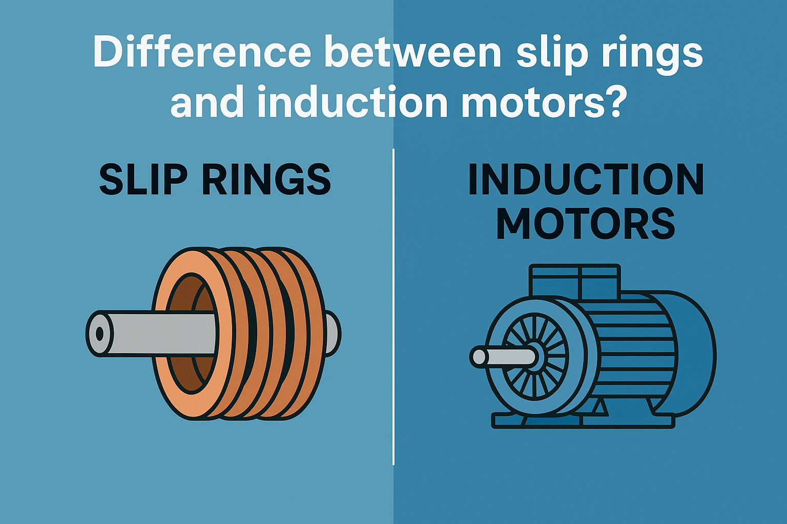
Difference between slip rings and induction motors? Slip Rings Definition A slip ring is an electromechanical device that allows the transmission of electrical power and signals from a stationary to a rotating structure. It is also known as a rotary electrical joint, collector, or electric swivel. Function The primary function of a slip ring is to ensure the continuous transfer of electrical signals, power, or data between stationary and rotating parts without causing twisting or tangling of wires. This is essential in systems that require continuous rotation and electrical connectivity. Parts Rotating Rings: Conductive metal rings, usually made from materials such as brass, silver, or gold-plated materials, that rotate along with the shaft. Stationary Brushes: Conductive brushes, typically made of graphite or precious metals, that maintain contact with the rotating rings to allow the flow of electrical current.   Types and Working Through Bore Slip Rings: Designed with a hole in the center for shaft mounting, allowing cables and hoses to pass through. Capsule Slip Rings: Compact design suitable for low-current or signal applications, where space is limited. High Current Slip Rings: Built for high-power transmission, often with robust insulation and larger brushes and rings to handle increased electrical loads.   Working: As the shaft rotates, the brushes slide along the surface of the rings, maintaining electrical contact. This sliding contact allows electrical signals or power to be transferred between the stationary and rotating components without interruption. Advantages Allows for continuous rotation without tangling of wires. Can transmit power and signals across rotating interfaces. Customizable to specific needs, including size, speed, and type of signal. Disadvantages Physical wear over time due to the friction between brushes and rings. Potential for electrical noise and signal degradation. Requires regular maintenance to ensure reliable operation. Uses Wind Turbines: Transfer power and signals from rotating blades to stationary components. Radar Antennas: Enable 360-degree rotation without interrupting electrical connections. Medical Equipment: Used in devices such as CT scanners for continuous data transfer during rotation. Industrial Machinery: Common in rotating tables, packaging machines, and automated systems that require continuous rotation. Induction Motors Definition An induction motor is an electric motor that operates on alternating current (AC) and utilizes electromagnetic induction to produce mechanical motion. They are also known as asynchronous motors because the rotor does not rotate at the same speed as the magnetic field. Function Induction motors convert electrical energy into mechanical energy through the interaction of a rotating magnetic field created in the stator and the induced currents in the rotor. This interaction produces torque, causing the rotor to spin and drive mechanical loads.   Parts Stator: The stationary part of the motor, consisting of laminated iron cores and windings of insulated wire that create a magnetic field when AC is supplied. Rotor: The rotating part, which can be a squirrel cage or wound type. It is placed inside the stator and is induced by the magnetic field, creating an opposing magnetic field that causes rotation. Bearings: Support the rotor and reduce friction during rotation. Cooling Fan: Helps dissipate heat generated during motor operation, improving efficiency and lifespan.   Types and Working Single-Phase Induction Motors: Operate on a single-phase power supply and are commonly used in household appliances. They are not self-starting and require an additional mechanism, such as a capacitor, to initiate rotation. Three-Phase Induction Motors: Operate on a three-phase power supply, generating a rotating magnetic field that induces current in the rotor. These motors are self-starting and provide higher efficiency and power output, making them suitable for industrial applications. Working: When AC power is applied to the stator windings, it creates a rotating magnetic field. This field induces a current in the rotor, which generates its magnetic field. The interaction between the stator and rotor fields produces torque, causing the rotor to turn and perform work. Advantages Simple and robust construction with fewer moving parts. High reliability and low maintenance requirements. Cost-effective and efficient for a wide range of applications. Disadvantages Speed is not easily controlled without additional components. Starting torque can be lower compared to other motor types. Efficiency decreases under light load conditions. Uses Industrial Machinery: Widely used in pumps, compressors, conveyors, and fans due to their durability and efficiency. Household Appliances: Found in devices like washing machines, refrigerators, and air conditioners. Electric Vehicles: Used in the propulsion systems of electric cars and hybrid vehicles due to their high torque and efficiency. HVAC Systems: Commonly employed in heating, ventilation, and air conditioning systems for their reliability and low maintenance.

What is a sensor?

What is a sensor? A sensor is a device that senses something. Today we have sensors that can see, feel, hear, smell, and even taste. Without sensors, our home and work lives would be quite difficult. For example, as you drive to work, the traffic lights at an intersection are controlled by sensors embedded in the road. These sensors detect your arrival at the intersection. As you approach the grocery store, the door automatically opens because of a sensor. In your plant, the batch process temperature and pressure are displayed and controlled as a result of output from Sensors.   Industrial sensors In the world of instrumentation and process control, we define a Sensor as a device that detects changes in physical, electrical, or chemical properties and produces an electrical output in response to that change.   Types of sensors What are the typical physical properties that sensors are detecting? Let’s name a few… Level, Temperature, Flow, Pressure, Speed, and Position.   Classification of sensors From a process control perspective, we can classify sensors as either Passive or Active. Passive sensors A Passive Sensor requires an external source of power to operate while an Active Sensor does not.   Active sensors A Thermocouple is an Active Sensor as it does not require any external power supply to operate. Active sensors examples As a thermocouple is exposed to an increase in temperature, it will develop an increasing voltage across it.   Another example of an Active sensor is a piezoelectric sensor.   Passive sensors examples A Resistance Temperature Detector (RTD) is a Passive Sensor. It is a device that’s resistance will change with a change in temperature. To take advantage of this change in resistance, an external supply, or an excitation circuit is required to produce a change in voltage.   Another example of a Passive sensor is a Strain Gauge.   Sensors in the industry Alright now that we’ve talked about different sensor types and the physical properties that they can sense, let’s discuss how they are used in the industry. Almost every sensor used in process control will be connected to a Transmitter because a sensor’s output needs to be conditioned or amplified. Here’s an example…We’ve already talked about a thermocouple and the voltage output created when it is heated. Unfortunately, the voltage output of a thermocouple is minuscule! In our example, the thermocouple will produce a voltage output from 8 mV to 18 mV over a 450 degree Fahrenheit change in temperature! In-process control, we condition that 8mV to 18mV thermocouple voltage and convert it to a 4 mA to 20 mA industry-standard signal that represents our controlled temperature range.  

Motor Starting DOL Reverse Forward Star Delta

What are the types of Motor Starting explain each with a Power and Control Diagram? What is a Motor Starter? The Motor Starter is a device used to start and stop the motor to which it is connected. A DOL (Direct On-Line) starter is normally used to start the motor. But for a heavy motor with more power, other advanced starters like Star-Delta, Soft Starter, and VFD Starter are used. Advanced starter (like Star-Delta, Soft Starter, and VFD Starter) applies less voltage to reduce the high initial current, this voltage reduction is for a short time. As the motor accelerates to its running speed, full voltage is applied to the motor. The motor starter provides other functionality also to protect the motor from any other fault like overload, single phasing, under-voltage, voltage unbalance, and stall protection. There are many types of starters used to start the motor, in this blog, we are going to see some basic motor starters and their conversion into PLC ladder logic. DOL STARTER DOL stands for Direct Online Starter, most commonly used in the industry to start the motor. In this method, full voltage is applied to the motor, but the starting current would be very high (usually 5-8 times more than its rated current). For a low-capacity motor, there is no need to reduce the voltage at the start. Although, it provides all other functionalities like overloading, single phasing, and low voltage. To develop the PLC ladder logic of the DOL starter, first, we have to look at the control circuit of this starter.   DOL Starter Advantages: Cost-Effective Simple in Construction Disadvantages: Initial high current Unable to use Heavy Motors Ladder Logic of DOL Starter   Forward/Reverse Starter Forward/Reverse starter is another starter used when we need to change the direction of the motor, through this starter, it is possible to operate the motor in both directions. Forward/Reverse starter works on the same principle as the DOL starter, but it has additional functionality to change the direction of the motor. Here you can find the control and power wiring of this starter.   Forward Reverse Starter Advantages: Cost-Effective Simple in Construction High Starting Torque Disadvantages: Initial high current Unable to use on Heavy Motors Ladder Logic of Forward-Reverse Starter   Star-Delta Starter Star-Delta starter is used for heavy motor applications like Pump, Blower, Crusher, etc. Star-Delta starter supplies a low voltage initially at the start, this reduces torque also. This starter uses a timer, contactor, overload, etc. In this starter, the Star connection is used at the start and the Delta connection is used for a normal run.   Star-Delta Starter Advantages: Low starting current Good for long acceleration time Disadvantages: Complex wiring Ladder Logic of Star-Delta Starter  

PLC Programming Instruction List

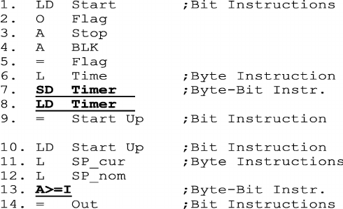
PLC Programming Instruction List Introduction Instruction List (IL) is a low-level programming language used in programmable logic controllers (PLCs). It consists of a series of instructions executed in sequence. Steps Read about Instruction List (IL) programming. Understand the basic IL commands for logic gates and mathematical operations.   Writing Simple IL Programs Logic Gates AND Gate: Y = A AND B LD A               ; Load A AND B            ; AND with B ST Y   ; Store result in Y   OR Gate: Y = A OR B LD A               ; Load A OR B               ; OR with B ST Y   ; Store result in Y   NOT Gate: Y = NOT A LD A               ; Load A NOT                ; NOT operation ST Y   ; Store result in Y   Mathematical Operations Addition: Y = A + B LD A               ; Load A ADD B            ; Add B ST Y   ; Store result in Y   Subtraction: Y = A – B LD A               ; Load A SUB B             ; Subtract B ST Y   ; Store result in Y   Multiplication: Y = A * B LD A               ; Load A MUL B            ; Multiply with B ST Y   ; Store result in Y   Division: Y = A / B LD A               ; Load A DIV B             ; Divide by B ST Y   ; Store result in Y           Complex IL Programs Examples IL Program for the logical expression Y = (A AND B) OR (C AND D) LD A               ; Load A AND B            ; AND with B OR (   ; Begin OR operation LD C               ; Load C AND D            ; AND with D )           ; End OR operation ST Y   ; Store result in Y   IL Program for the mathematical expression Y = (A + B) * (C – D) LD A               ; Load A ADD B            ; Add B MUL (      ; Begin multiplication operation LD C               ; Load C SUB D            ; Subtract D )           ; End multiplication operation ST Y   ; Store result in Y             Practice Exercises Exercises Write an IL program for the logical expression Y = NOT(A OR B) AND C. LD AOR BNOT AND CST Y Write an IL program for the mathematical expression Y = (A * B) + (C / D). LD AMUL BST P1LD C DIV DST Y2LD P1ADD P2ST Y  

What is an HMI System?

What is an HMI System? A Human-Machine Interface (HMI) is a user interface that allows humans to interact with machines, systems, or devices. In the context of industrial automation, HMI systems are crucial as they provide operators with a graphical interface to monitor, control, and manage machines and processes. These systems are typically found in industries such as manufacturing, energy, water treatment, and transportation. 2. Key Components of HMI Systems: Display Interface: The HMI display, usually a touch screen or a computer monitor, shows real-time data, process status, and controls. It visualizes data in the form of charts, graphs, alarms, and controls. Control Panels: HMIs often include control panels where operators can start, stop, and adjust various parameters of the machinery or processes they manage. Communication Interface: HMIs communicate with Programmable Logic Controllers (PLCs), sensors, and other automation devices through communication protocols like Ethernet, Modbus, or Profibus. 3. Functions of HMI Systems: Monitoring: Operators can monitor real-time data such as temperature, pressure, flow rates, and production levels. Control: HMI systems allow operators to control processes and machinery by sending commands to PLCs and other automation systems. Alarm Management: HMIs can display alarms when a process deviates from normal operating conditions, allowing operators to take corrective actions. Data Logging and Reporting: HMIs can log process data and generate reports for analysis and troubleshooting. Benefits of HMI Systems: User-Friendly Interface: Provides an intuitive and easy-to-use interface for operators. Real-Time Monitoring: Allows for real-time visibility into processes, enabling quick decision-making. Improved Efficiency: Streamlines operations by providing centralized control and monitoring. Reduced Downtime: With effective alarm management and real-time monitoring, potential issues can be identified and resolved quickly.

What is a DCS System?

What is a DCS System? Definition of DCS: A Distributed Control System (DCS) is an automated control system that consists of a network of controllers, field devices, and human-machine interfaces (HMIs) that are distributed throughout a plant or facility. DCS systems are commonly used in large-scale industrial processes where centralized control is not feasible or efficient. Components of a DCS: Controllers: Distributed throughout the plant, these controllers manage and control different parts of the process. Each controller typically handles a specific section or unit of the process. Field Devices: Sensors, actuators, and other devices that interface with the physical processes, providing data to the controllers and executing control commands. HMI: The interface through which operators interact with the system. It provides visualization of the process, control capabilities, and alarm management. Communication Network: The backbone of a DCS, enabling communication between controllers, field devices, and HMIs. Common protocols used include Ethernet, Profibus, and Fieldbus. Key Features of DCS: Decentralized Control: Control functions are distributed across multiple controllers, each responsible for a specific part of the process. Scalability: DCS systems can easily scale to accommodate new controllers or processes as the plant expands. Redundancy: DCS systems often include redundant controllers and communication paths to ensure reliability and uptime. Integration: DCS systems are designed to integrate with various automation systems, sensors, and actuators within the plant. Applications of DCS: Process Industries: DCS is widely used in industries like oil and gas, chemical processing, power generation, and water treatment, where complex processes need to be managed and controlled. Large-Scale Operations: DCS is ideal for large-scale operations where centralizing control would be impractical. Benefits of DCS: Improved Process Control: DCS allows for precise control of complex processes, leading to increased efficiency and product quality. Enhanced Reliability: With distributed control and redundancy, DCS systems are highly reliable and reduce the risk of plant-wide failures. Centralized Monitoring: Even though control is distributed, operators can monitor and manage the entire process from a central HMI. Flexibility: DCS systems can be easily adapted to changes in process requirements or expansions in the plant.